Anbernic RG35XX-H USB-C Charging Mod
I recently acquired an Anbernic RG35XX-H to play some retro games for some old systems I own. But since my A/V setup is all nicely tucked away in a rack, so nothing is visible inside our house, I needed something to play these “on the go”.
I’m very happy with the device, but apparently, for safety, it’s better to always charge with a USB-A to USB-C cable (apparently). The issue lies in the fact that these devices (seemingly this became apparent from some RG35XX-SP/Plus devices), when powered via USB-C to USB-C cable; can mistake a USB-C charger, for a device that needs power supplied to it. This can result in overheating / failures / fire of either the device or the charger itself.
Technically, not that big of a deal if you just use USB-A to USB-C cables (these don’t have CC1/CC2.. we’ll get to that), but most of my chargers at home use USB-C to USB-C.
To fix this on the RG35XX-H, you’ll need:
- Good eyesight or a microscope (we’re dealing with 0402 components)
- Two 5.1k resistors in 0402
- A hex and Philips precision screwdriver
- Your soldering iron
- Flux
- Something to clean the board afterward
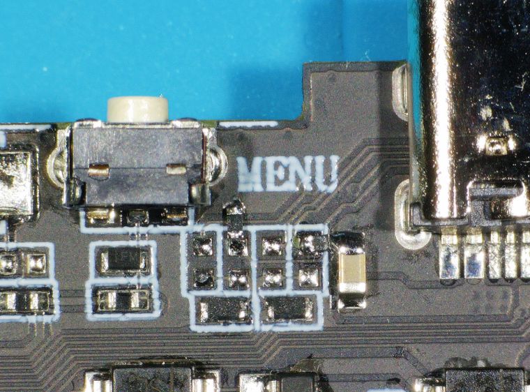
Now, on to those CC1 / CC2 lines (And SBU1/SBU2). These pins are all connected via a zero-ohm resistor and tied together on this motherboard. They can be found to the left of the “DC/OTG2”-port:
From left to right on the four pads below the “Menu” silkscreen: SBU / CC / SBU / CC.
This is not according to standard. Anbernic has tied this to a sense circuit, to still be able to provide power on that port as well. The problem is, that this gives a voltage that is “approximate” to what a charger expects on the CC pins, so it starts providing power. However, by having CC1 and CC2 tied together, and using cables with an “E-Marker” (e.g. higher spec USB-C cables), the device can be detected as a peripheral that doesn’t need power, and thus the device fails to charge.
On the other hand, the device, because of having CC1 and CC2 tied together, AND by using an “E-Marker” cable, will SUPPLY 5V, rather than consume it, because the sense circuit isn’t clever enough. Cue a bad scenario.
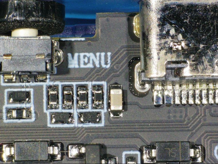
This can be fixed by removing the zero-ohm resistors connecting CC1/CC2/SBU1/SBU2 together; and connecting 5.1k resistors to ground, on each CC pin. But be aware: the device will NOT provide 5V to devices on that port anymore.

As you can see, the modifications are on pads two and four. For pad two, scratch a bit of the solder mask on the ground plane away, and you can nicely solder your 0402 5.1k resistor. For pad four, you connect it to the ground of that capacitor on the 5V line.
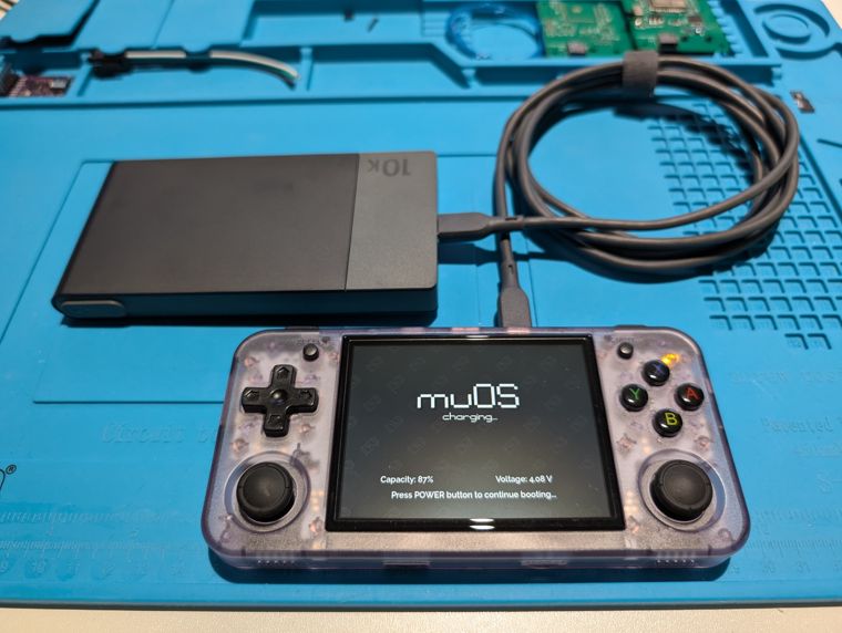
And there you have it, a perfectly safe RG35XX-H, charging on a USB-C PD power bank, with an E-Marker cable, and not overheating or catching fire:
BONUS TIP - You can find a most excellent case for this device over at Printables.com - it’s made by “Joshua C” and he has an Etsy shop. You can print it yourself, or opt to buy one.
Happy modding! - 73 de ON8AD


